Development Region II

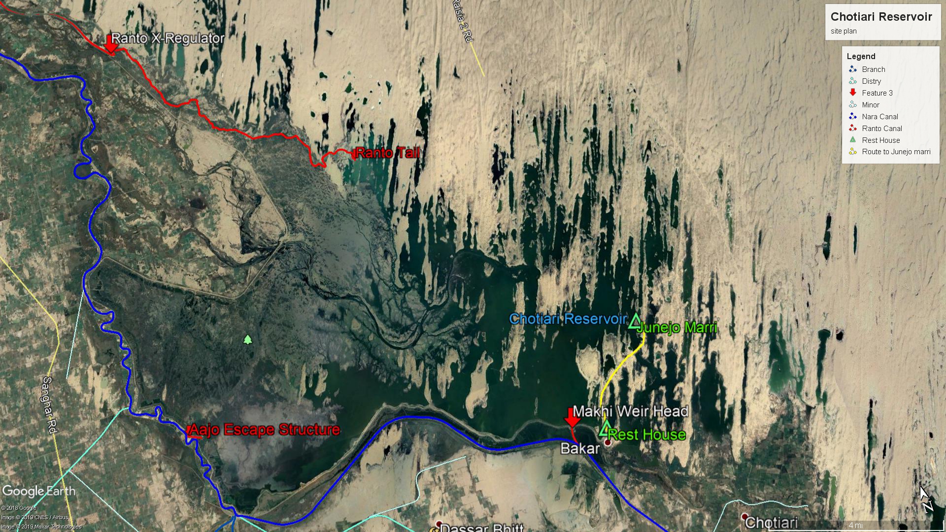
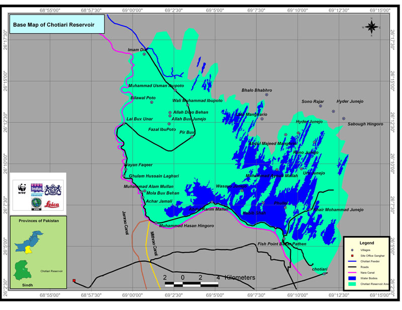
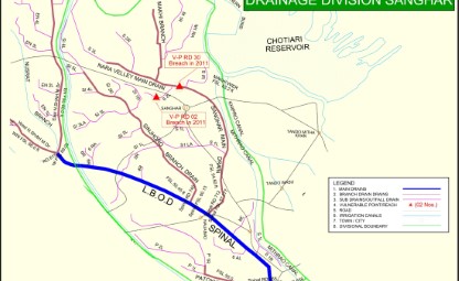
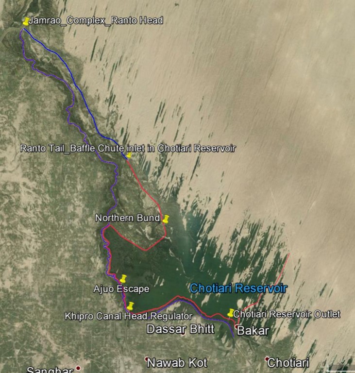
INTRODUCTION : The Chotiari Reservoir is a strategically located off-canal storage reservoir situated approximately 20 miles east of Sanghar, within the graticule of N260 5' - 260 16' E 690-0 to 690 11'. It comprises several natural depressions or lakes, primarily Makhi and Baqar, enclosed by the Larkana-Naushehro Feroze Canal (LNC) and Thar Desert sand dunes. The reservoir's construction was commissioned in 2003 to increase the storage capacity of these lakes and enhance irrigation supplies to the Lower Nara Canal (LNC) command area. This introduction provides an overview of the geographical location and purpose of the Chotiari Reservoir.
Objective : The primary objective of the Chotiari Reservoir is to augment irrigation supplies to the land improved by the construction of the drainage system under the Left Bank Outfall Drain (LBOD) Stage-1 project. The reservoir acts as an off-canal storage facility, with its inflows controlled by the availability of excess water at the Sukkur Barrage and Jamrao head. By increasing the storage capacity of the lakes and storing water in the Chotiari Reservoir, the objective is to provide a reliable water source for the Lower Nara Canal, benefiting the Jamrao System.
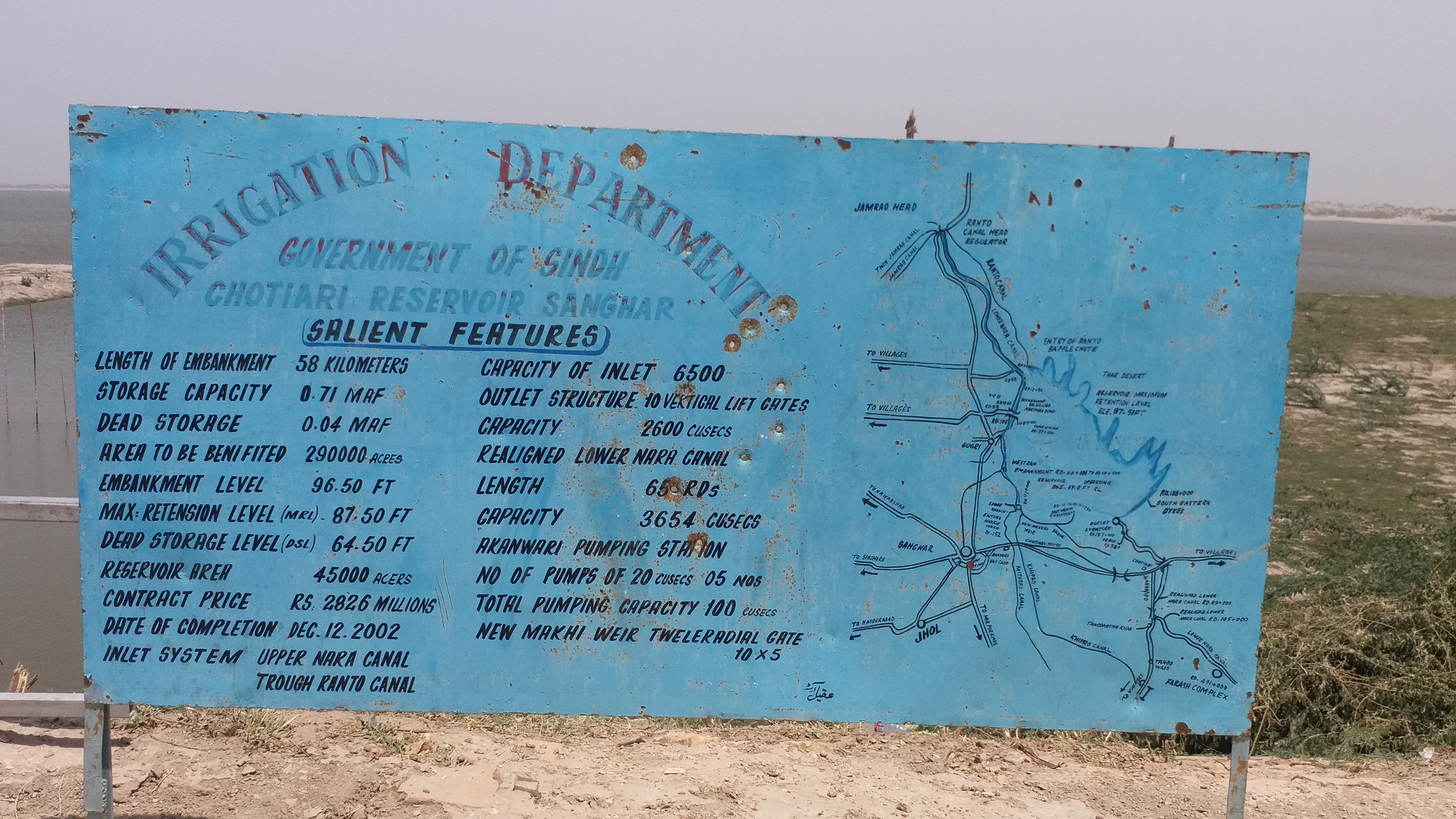
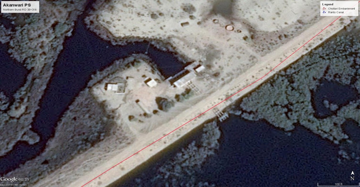
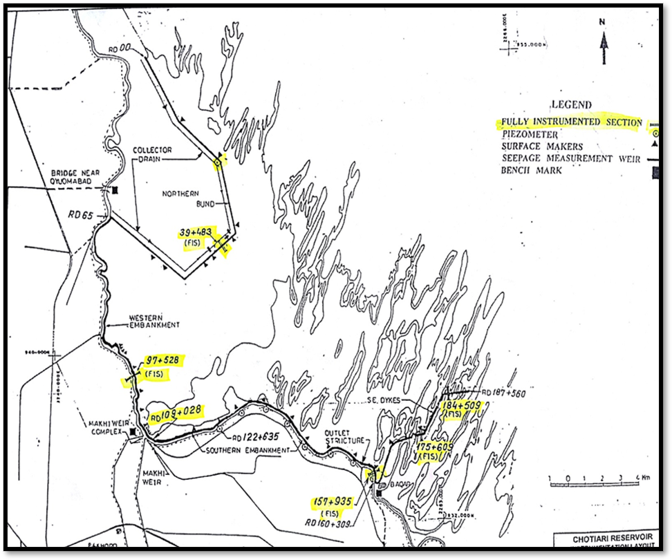
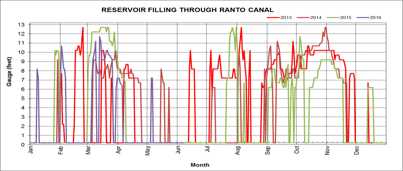
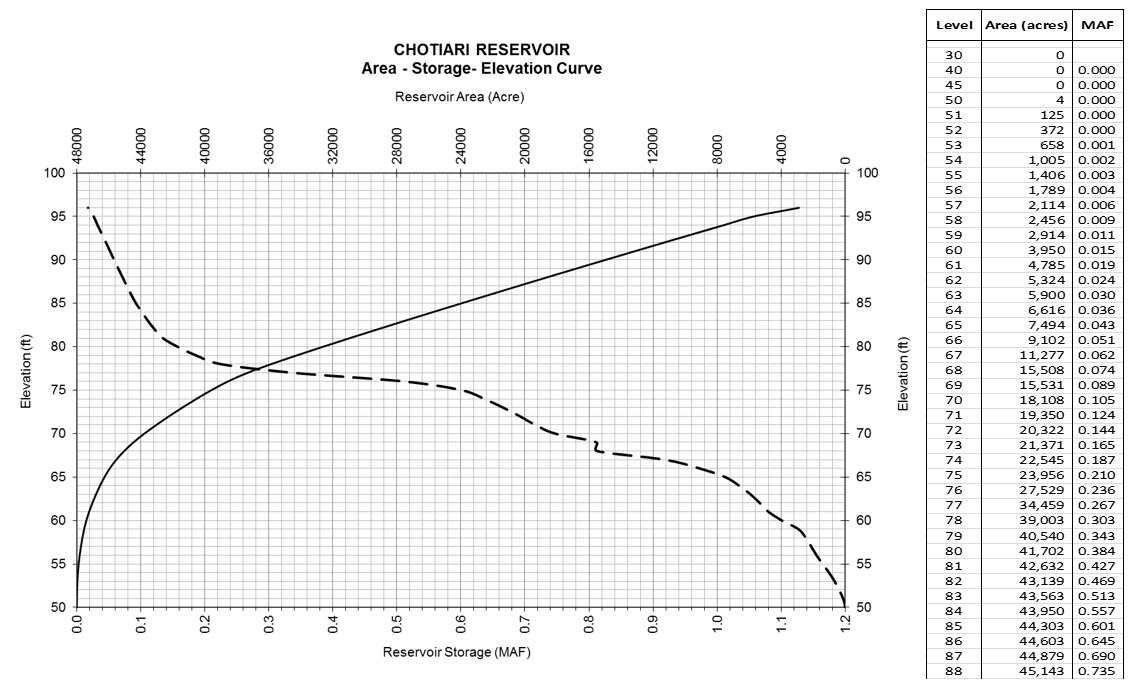
Role : The reservoir plays a vital role in the water management system by receiving water from the Ranto Canal and the Aujo Escape, which are off-takes from the Jamrao Head and Makhi Complex respectively. With a significant embankment stretching 35.5 miles, the Chotiari Reservoir has one of the world's longest reservoir embankments. It stores 0.71 million acre-feet (MAF) of water, covering an area of 78 square miles at the Normal Pool Level of 87.5 feet. The Live Storage of the reservoir is 0.62 MAF. The LBOD-1 project further increased the storage capacity to 0.71 MAF to benefit the Jamrao System indirectly by feeding the Lower Nara Canal through the enhanced storage of the Chotiari Reservoir, as a direct transfer to the Jamrao system was not feasible.
In summary, the Chotiari Reservoir serves as a crucial off-canal storage facility, strategically located to provide irrigation supplies to the Lower Nara Canal command area and support the drainage system under the LBOD Stage-1 project. It plays a significant role in water management and aims to enhance water storage capacity to benefit the Jamrao System indirectly through the Upper Nara Canal.
| Mean Annual Max. Wave | 05 ft. |
| Ranto stretched flow (7800 Cfs) for 6 days | 02 ft. |
| 100-y return 30 days rainfall + Ops failure | 02 ft. |
| Controlling Design Levels therefore are; | |
| Top of Embankment | RL 96.5 ft. |
| Normal Res. Level | RL 87.5 ft. and |
| Max. Drawdown Level | RL 69 ft. |
| At Normal Pool Level of | 87.5 ft. | 0.71 MAF |
| At Elevation of | 89.5 ft. | 0.80 MAF |
| At Elevation of | 91.5 ft. | 0.89 MAF |
Any of the above two situations appear to be a remote probability, unprecedented in the history of operations of Irrigation Dept.
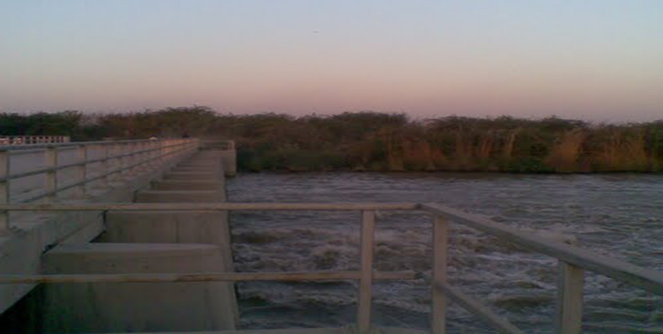
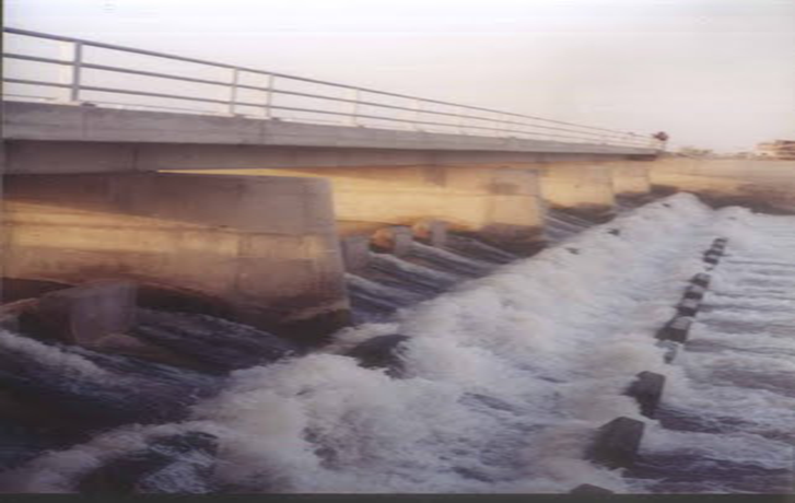
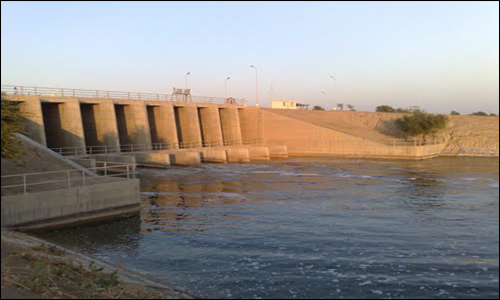
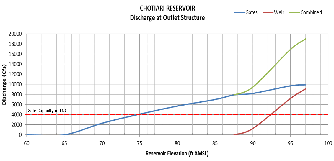
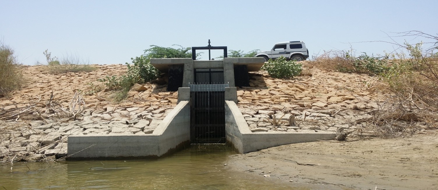
The Chotiari Reservoir Outlet Structure is situated at RD 156+813 on the Southern Embankment, specifically RD 199+805 of the Larkana-Naushehro Feroze Canal (LNC). The outlet structure is designed to discharge a maximum flow rate of 2,600 cubic feet per second (Cfs) into the LNC and is controlled by ten vertical undershot gates. The gates' sill is located at RL 64.5 ft., which is below the minimum drawdown level of 69 ft. At the normal pool level of 87.5 ft., with the gates fully open, the structure has the capacity to discharge 7,816 Cfs.
Apart from controlling releases into the LNC, the outlet structure also serves as a spillway. It includes an uncontrolled weir located above the gates, with its crest at RL 87.5 ft., corresponding to the normal pool level. When the reservoir reaches the surcharge reservoir level of 89.5 ft., combined with the gates fully open, the structure can discharge 9,358 Cfs. During the months of July and August, when the reservoir is expected to be full, the gates will remain closed, and the reservoir level will be safe up to an elevation of 91.5 ft. With the gates fully open under this condition, the structure can pass a combined discharge of 11,720 Cfs.
In the event that the reservoir rises to an elevation of 94.5 ft., which is just 2 ft. below the embankment crest, the structure is capable of discharging 16,184 Cfs. However, under normal circumstances, except in emergencies, the release from the reservoir to the LNC will not exceed 2,600 Cfs. It is important to note that water should not typically be released from the Chotiari Reservoir when the water level is at or below its dead storage level of 69 ft. If water still needs to be released to the LNC, the gates should be kept open until it stops at RL 64.5 ft., which is the sill of the outlet. The outlet structure plays a critical role in managing the water flow from the reservoir and ensures controlled discharge into the LNC while maintaining the reservoir's safety and operational efficiency.

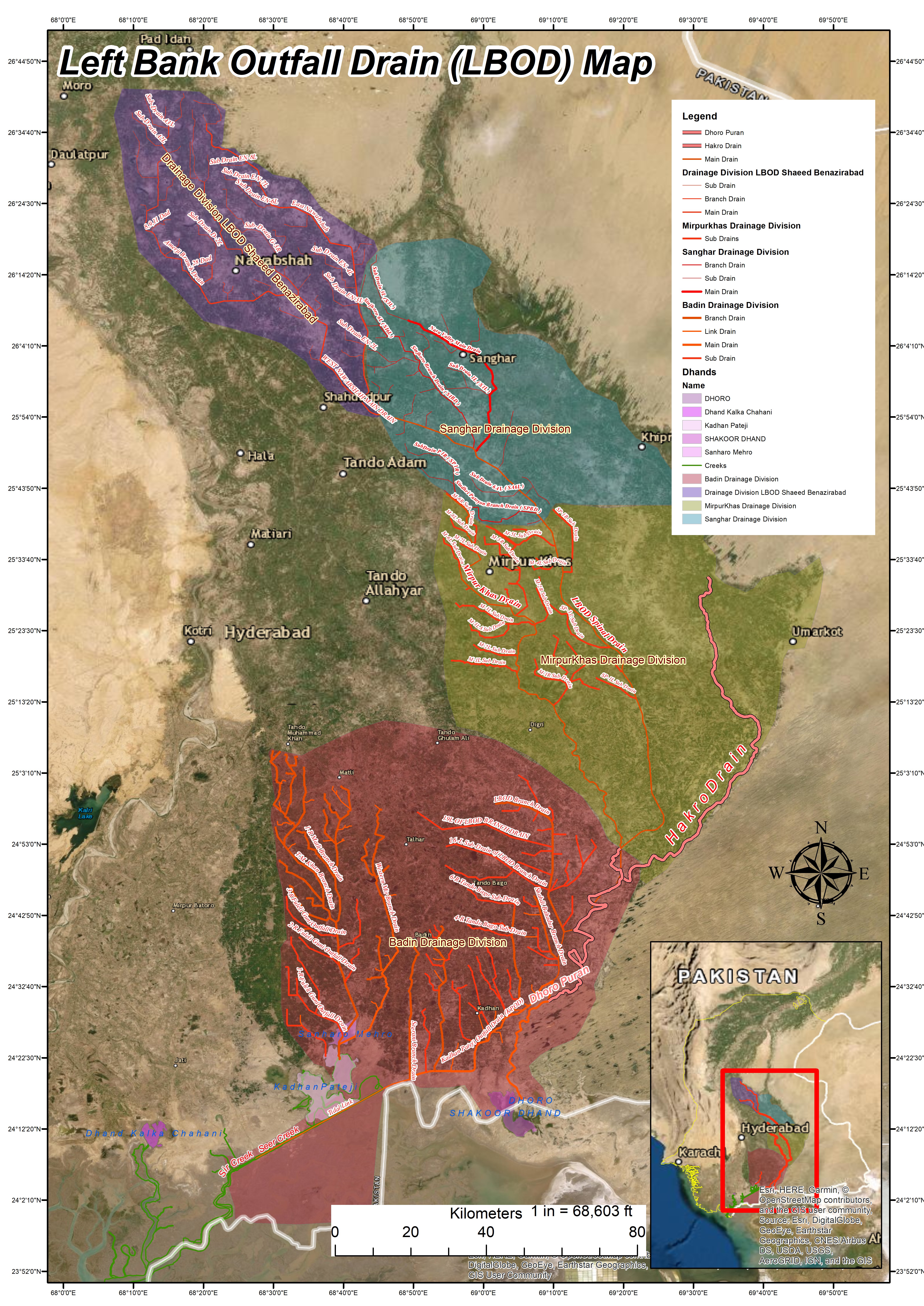
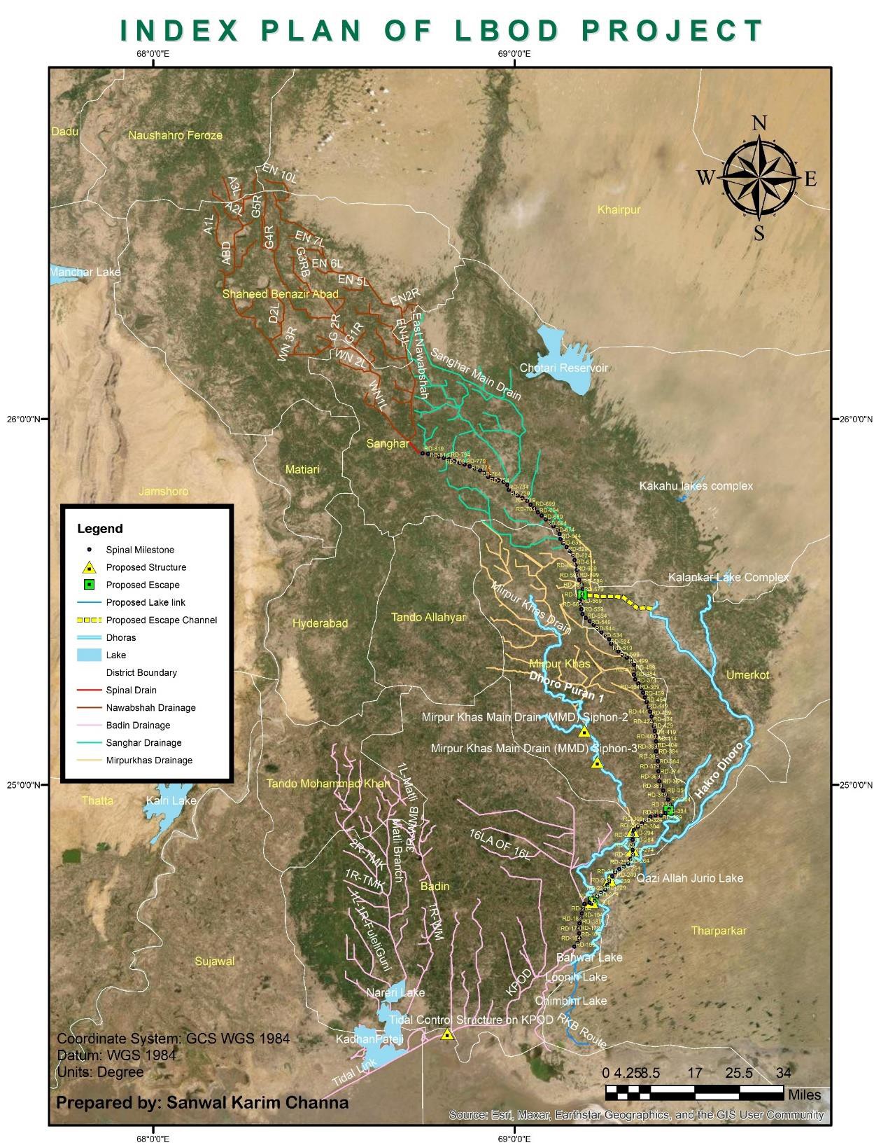
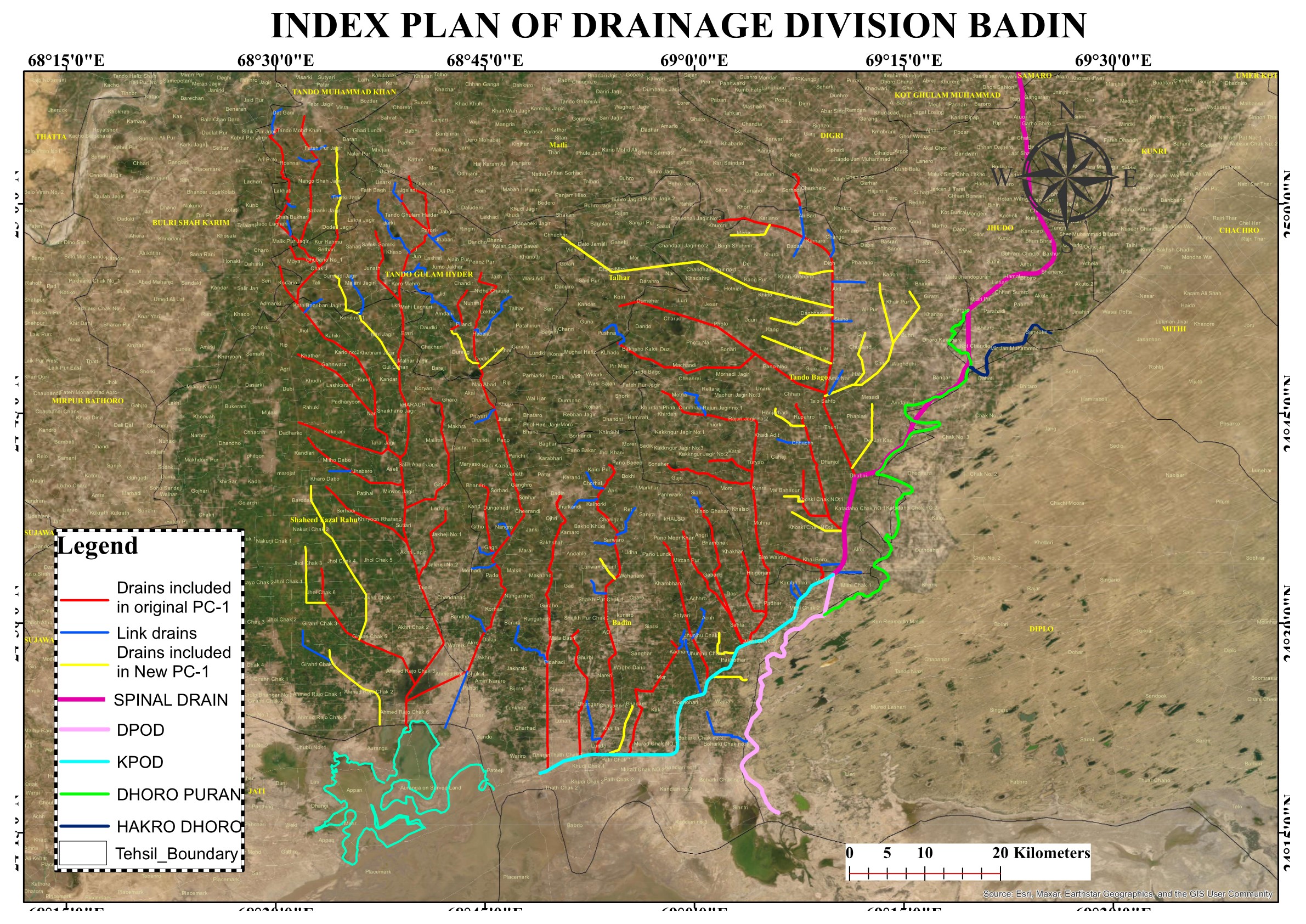
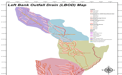
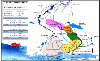
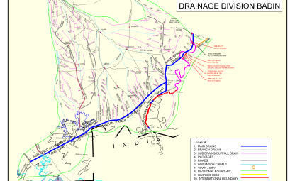
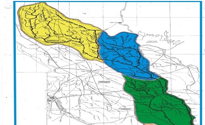
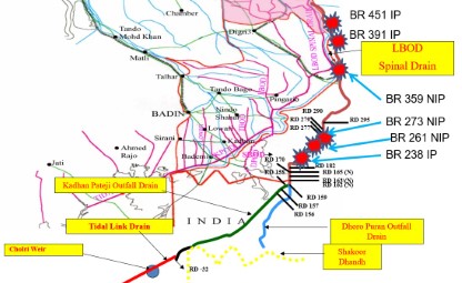
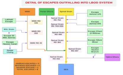
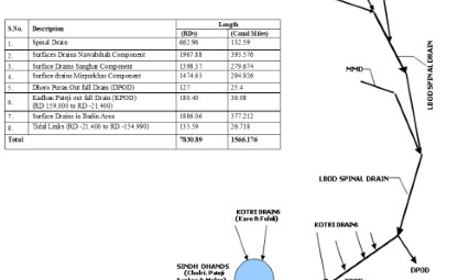
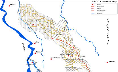
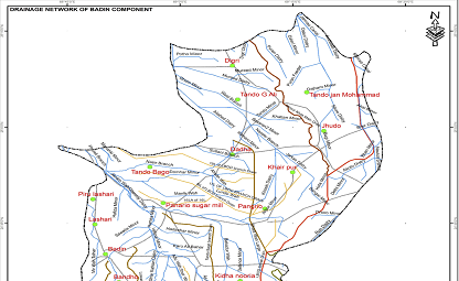
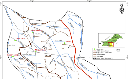
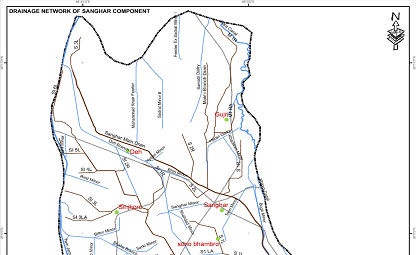
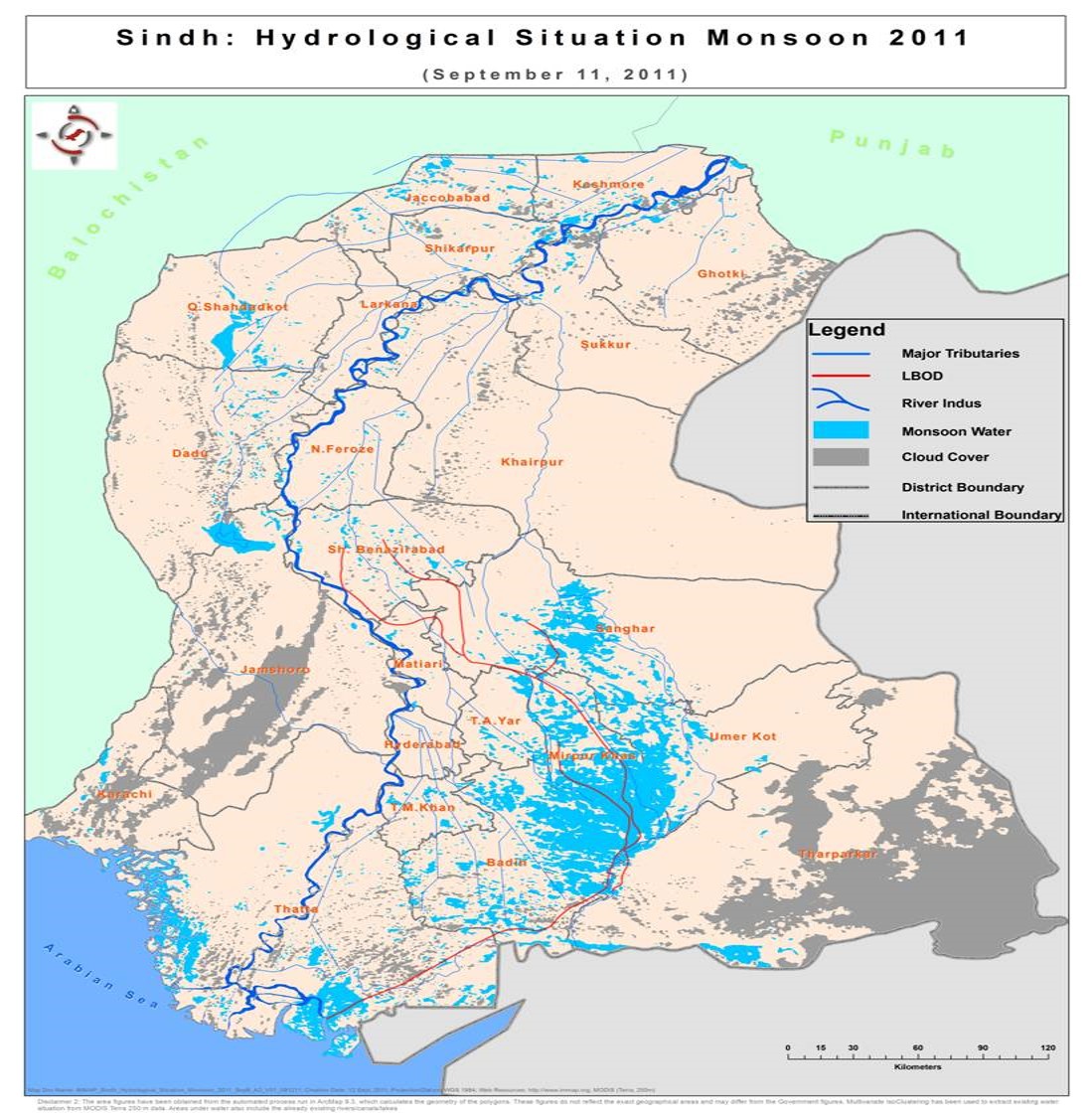
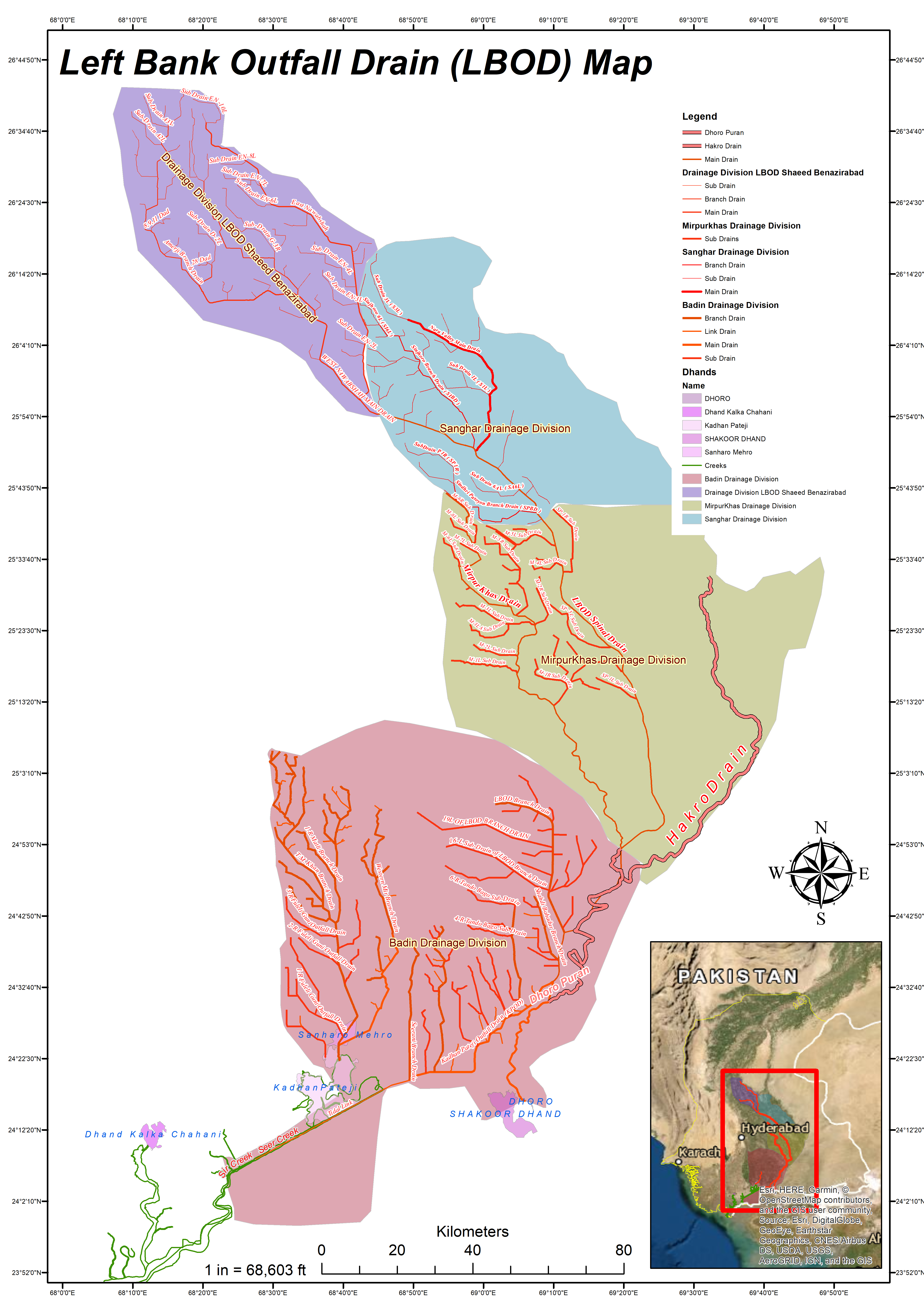
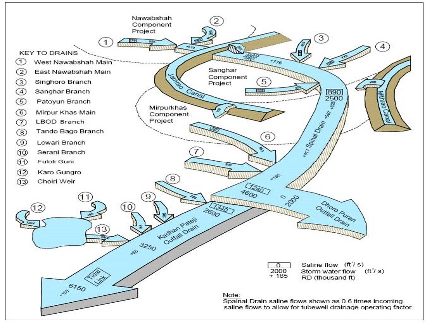
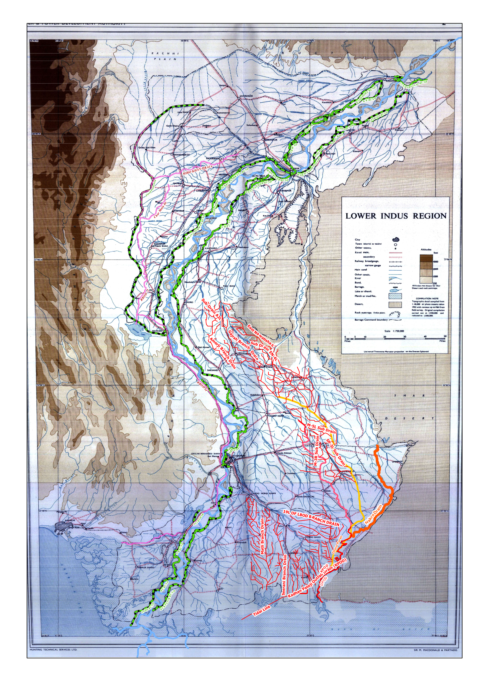
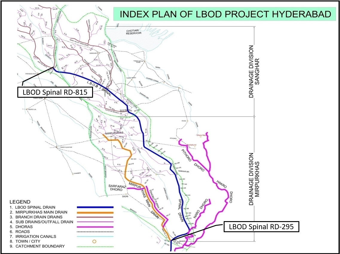
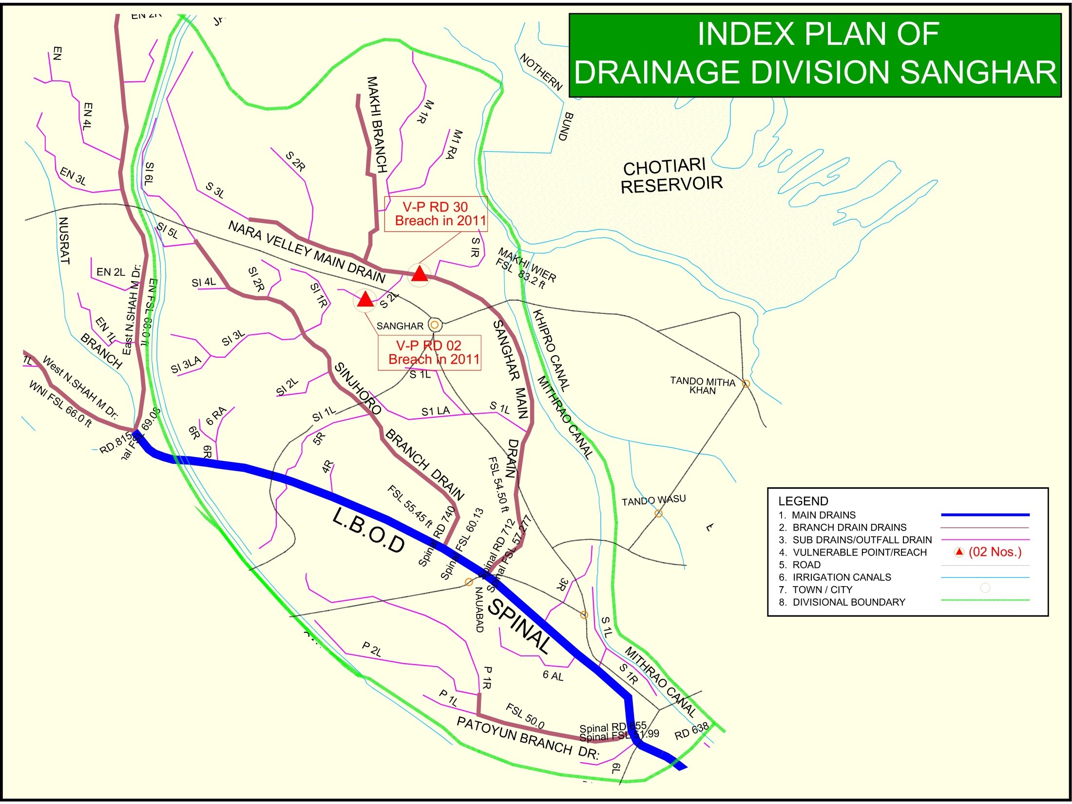
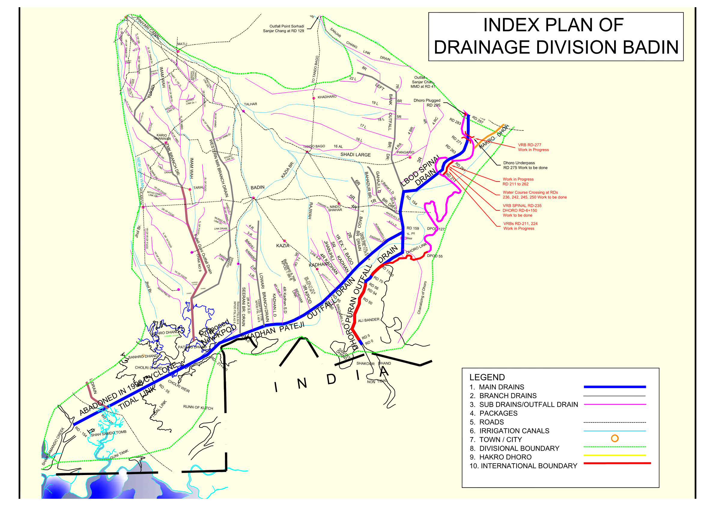
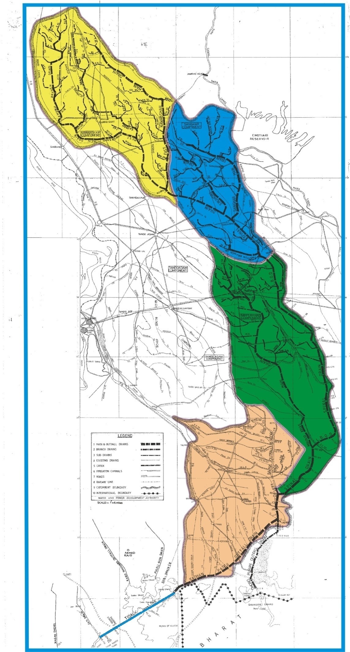
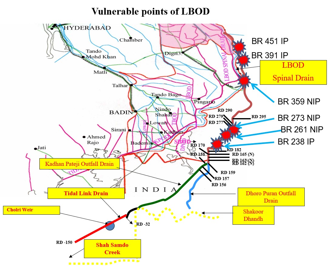
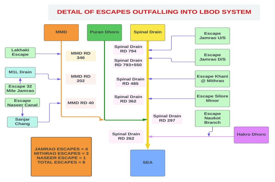
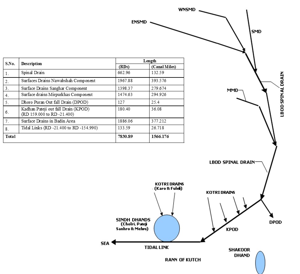
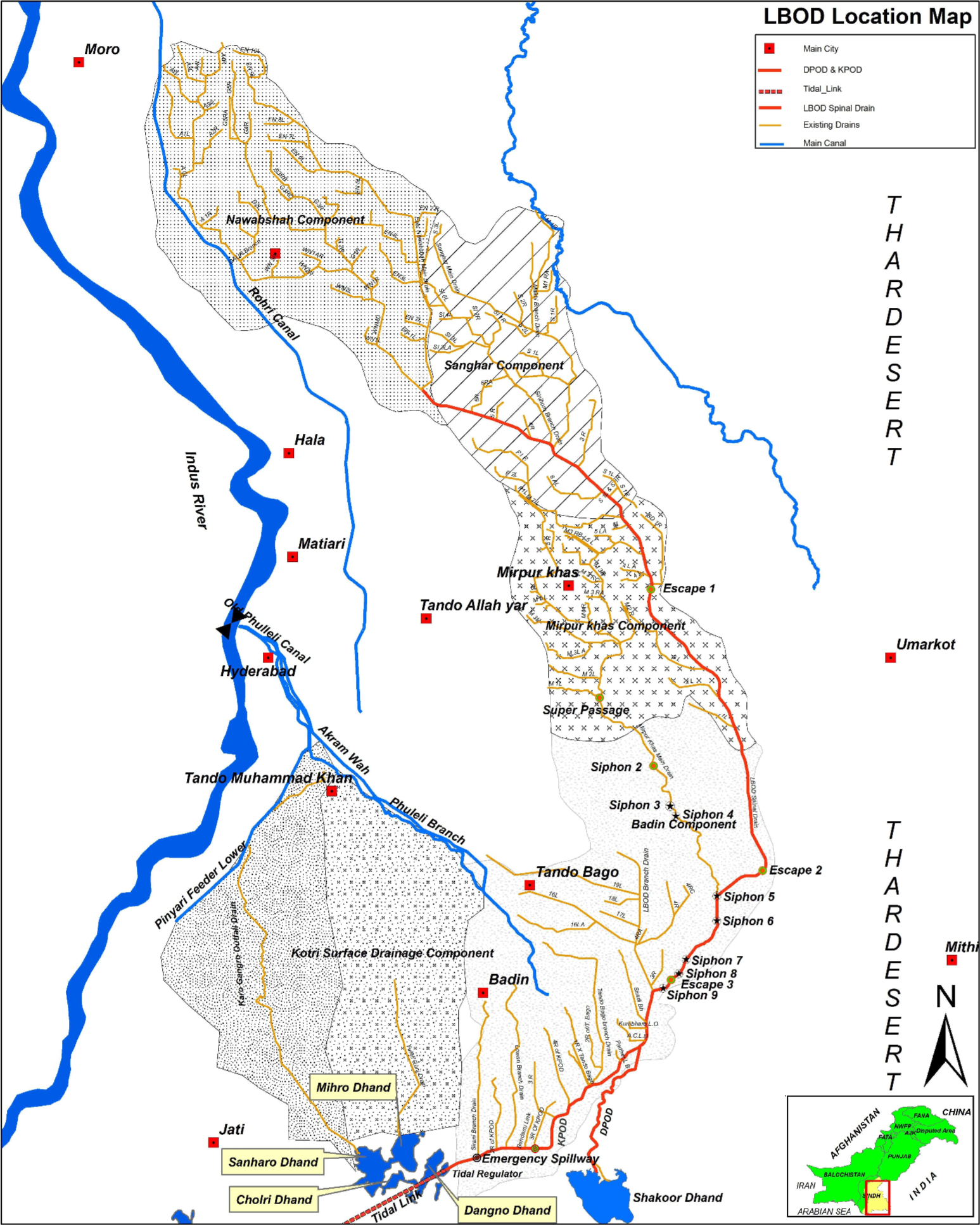
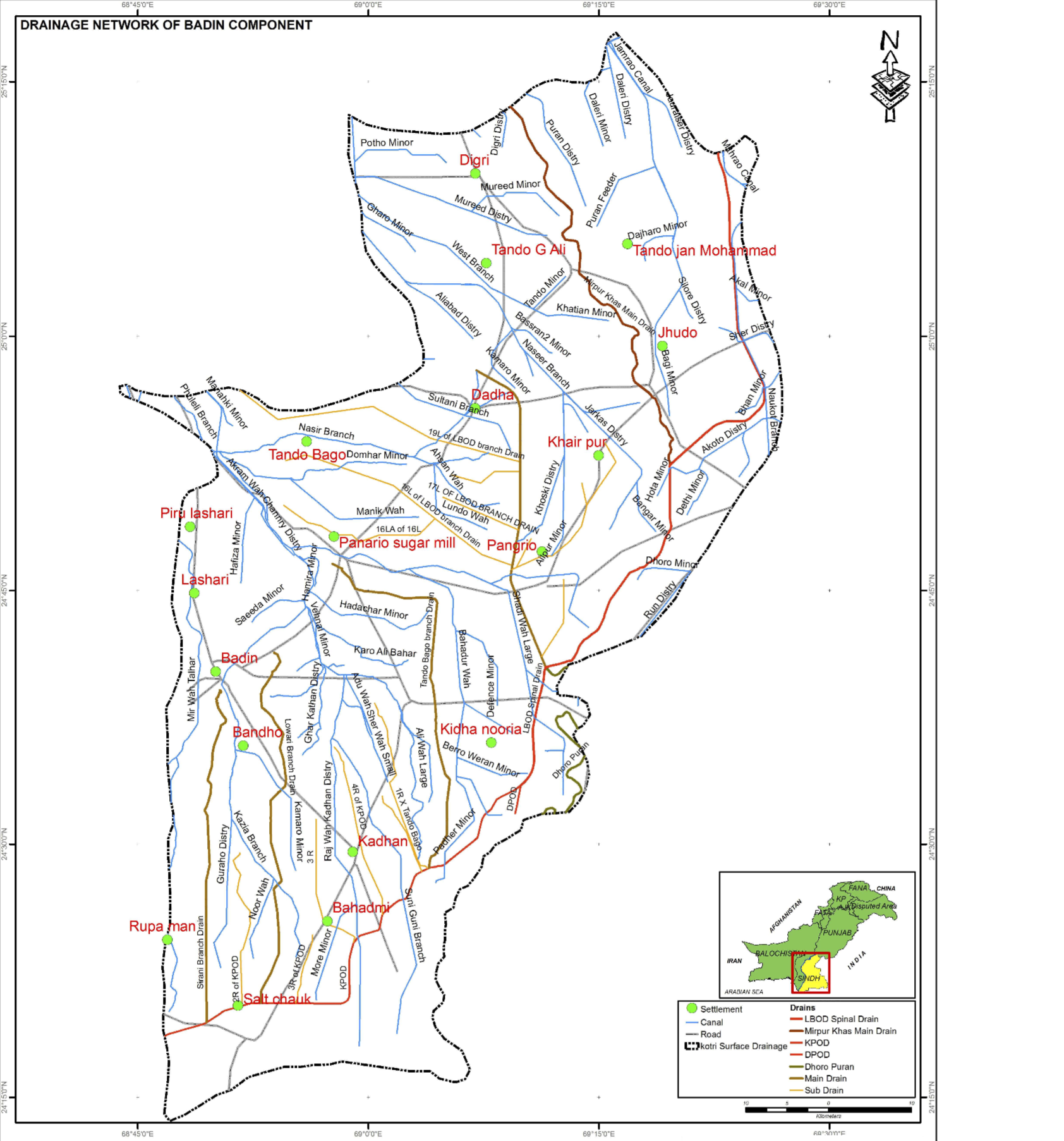
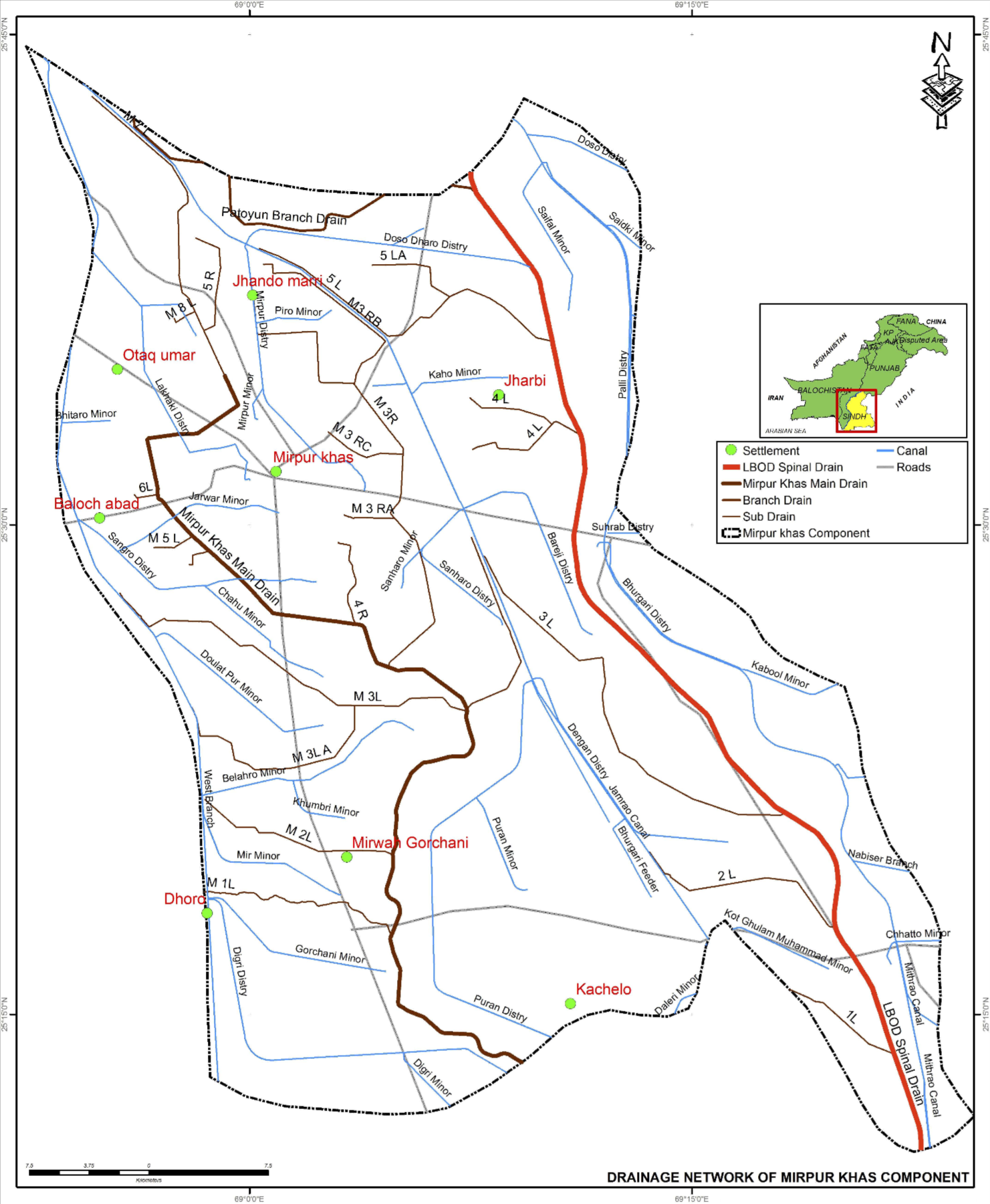
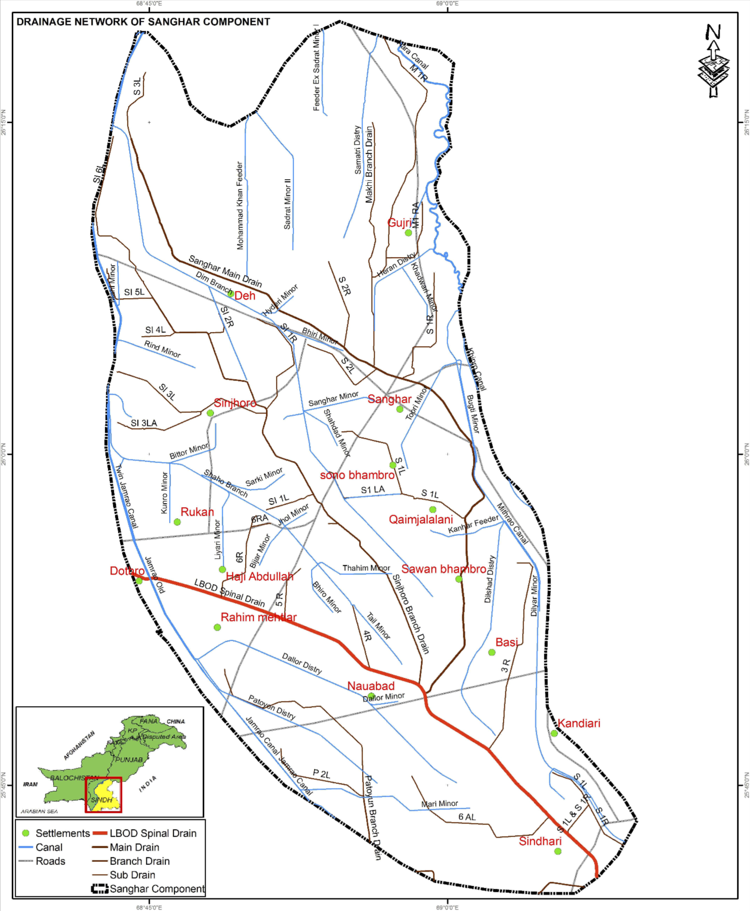
Background : The Left Bank Outfall Drain (LBOD) Project, approved by the International Development Association (IDA) on December 13, 1984, received a credit of $150 million. LBOD Stage I, implemented between 1984 and 1997, aimed to address waterlogging and salinity issues in 1.27 million acres across Shaheed Benazirabad, Mirpurkhas, Sanghar, and Badin Districts. The project's key component is the Spinal drain, which connects the drainage network to the sea through a Tidal Link. The LBOD spinal drain collects excess drainage and distributes it through a weir to two branch drains, the Kadhan Pateji Outfall Drain (KPOD) and the Dhoro Puran Outfall Drain (DPOD). The system was designed to direct highly saline drainage into the KPOD and ultimately to the sea via the 26-mile long canal known as the Tidal Link.
Introduction : The LBOD Project, initiated in 1984, aimed to mitigate waterlogging and salinity issues in several districts by establishing a drainage network connected to the sea through the Spinal drain and Tidal Link. However, concerns about potential ecological impacts arose regarding the Tidal Link, leading to the construction of protective measures such as raising the northern side and building the Cholri weir. Despite these efforts, operational challenges emerged, including erosion, scouring, and the collapse of a section of the Cholri weir. In 1999, a catastrophic cyclone caused severe damage, exacerbating the deterioration of the Cholri Weir and breaching the Tidal Link embankment. As a result, the LBOD has transformed into a "new river," forming an estuary and affecting coastal areas with visible tidal fluctuations. Adapting to this evolving process requires continuous hydraulic and environmental monitoring.
Objective : The objective of the Project is to alleviate waterlogging and salinity issues in Shaheed Benazirabad, Mirpurkhas, Sanghar, and Badin Districts. The project effectively managing excess drainage through the Spinal drain, which directs high salinity drainage into the Kadhan Pateji Outfall Drain (KPOD) and ultimately to the sea via the Tidal Link. However, challenges such as ecological impacts, structural integrity, and the unpredictable transformation of the LBOD into an estuary persist.
LBOD Administrative Transformation : The LBOD Spinal drain was initially handed over to the Irrigation Department of the Government of Sindh in 1993. However, the system faced difficulties and caused damages during heavy rains in the monsoon of 1994. Consequently, the system was returned to the Water and Power Development Authority (WAPDA) in 1995. On February 1, 2002, WAPDA transferred the LBOD System back to the Irrigation Department/Sindh Irrigation and Drainage Authority (SIDA).
The LBOD Spinal drain was initially handed over to the Irrigation Department of the Government of Sindh in 1993. However, the system faced difficulties and caused damages during heavy rains in the monsoon of 1994. Consequently, the system was returned to the Water and Power Development Authority (WAPDA) in 1995. On February 1, 2002, WAPDA transferred the LBOD System back to the Irrigation Department/Sindh Irrigation and Drainage Authority (SIDA).
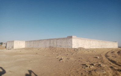
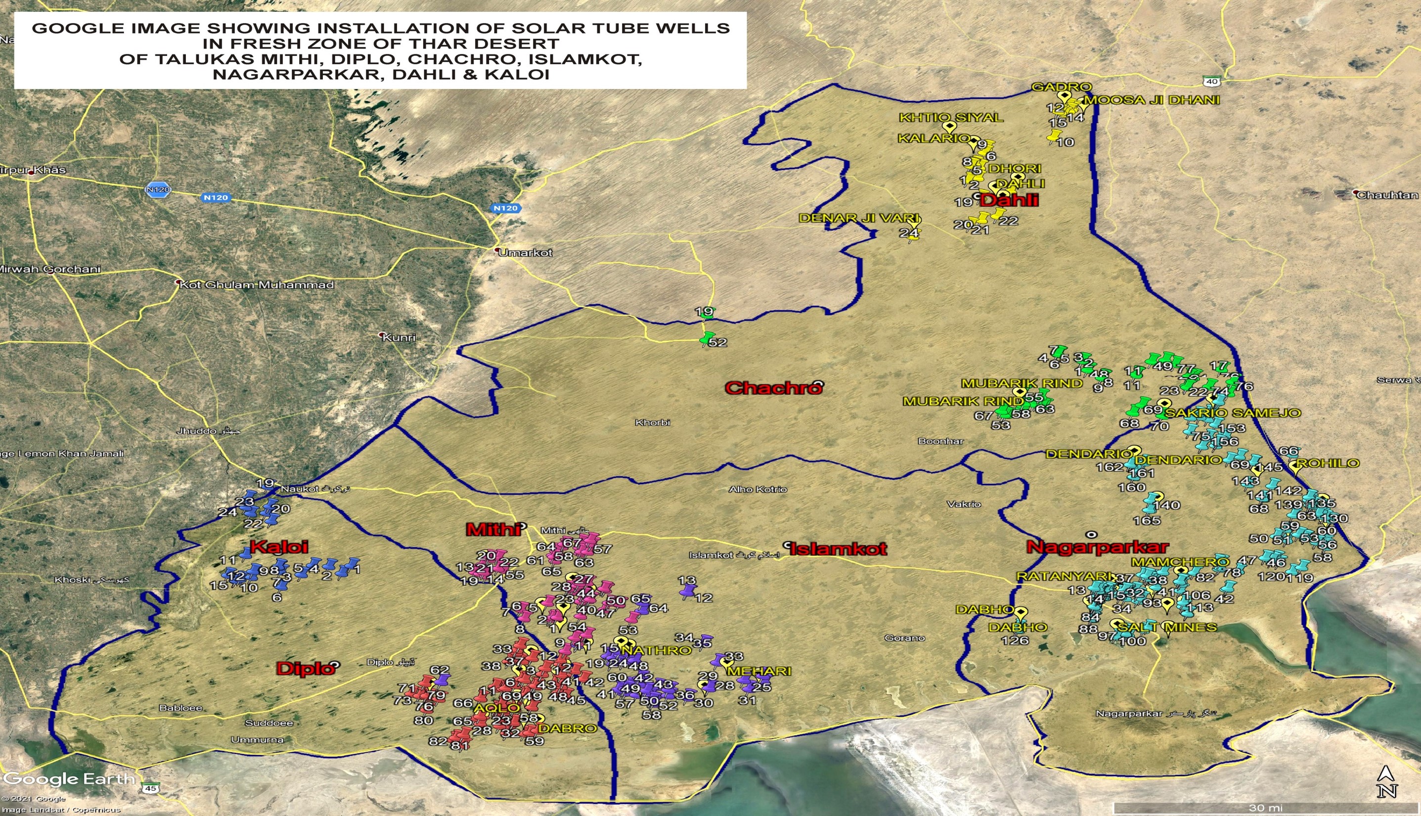
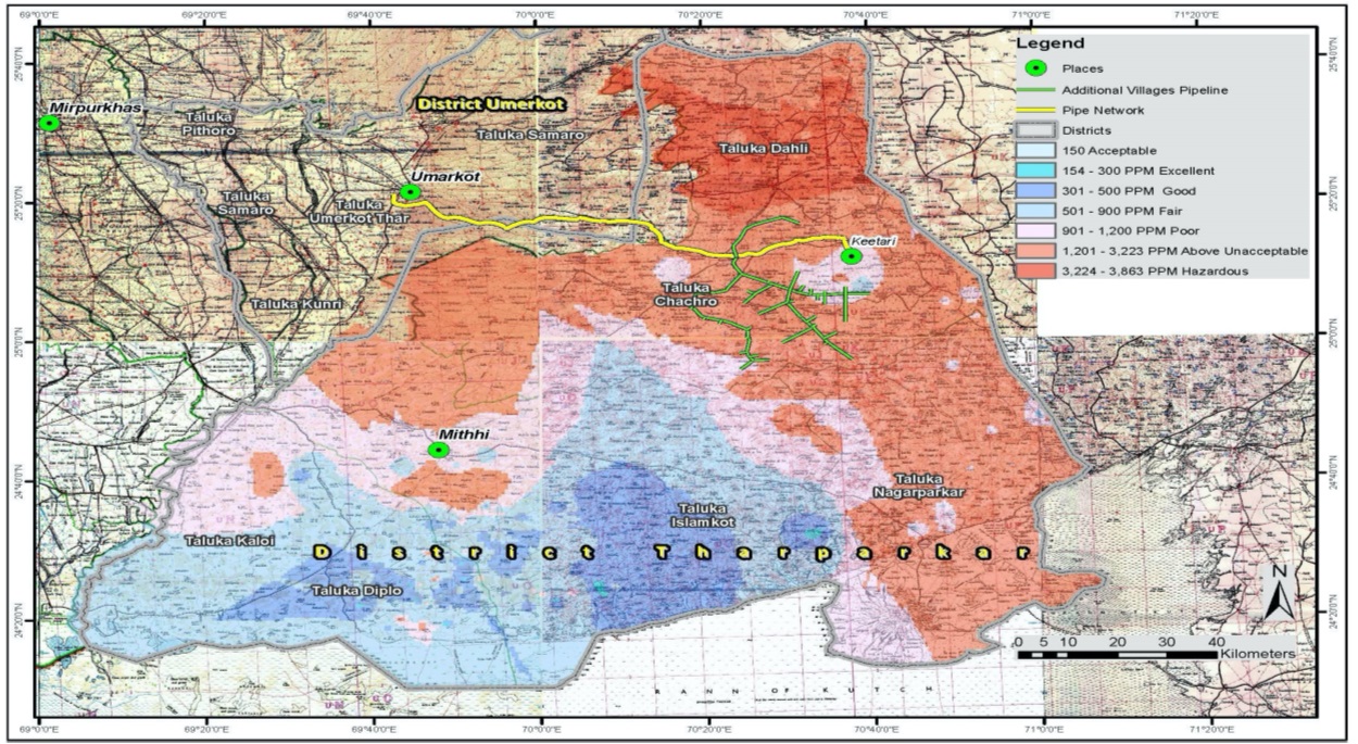
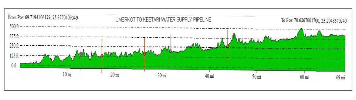
Providing Water from Kot Wah of Umer Kot to Keetari Taluka Chachro via Dhalo Jo Tar, Kaplore, Viklore Tar, Budha Sandha, Vechlo Par, Ratan Jo Tar and Constructing of Underground Reservoirs
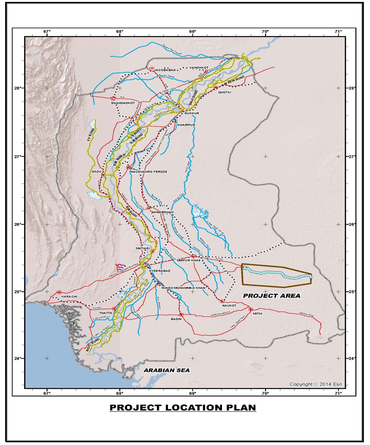
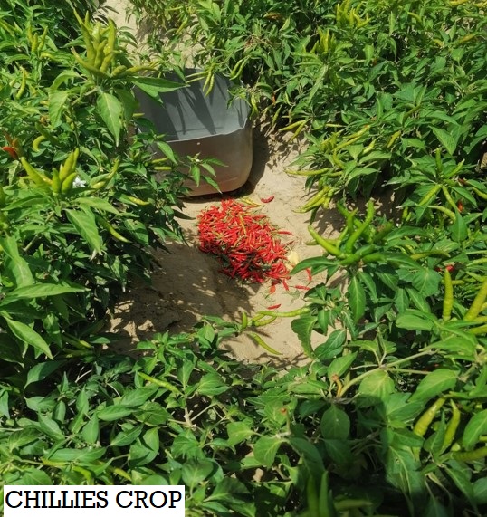
Tharparkar, a vast district spanning over 20,000 square kilometers, is located in Pakistan's southern Sindh province. As Pakistan's largest district and the 18th largest desert in the world, Tharparkar presents a juxtaposition of beauty and adversity. Behind the alarming mortality figures lies a deeper set of issues, including water scarcity, poverty, and illiteracy, which pose significant challenges to the 1.5 million people residing in this region.
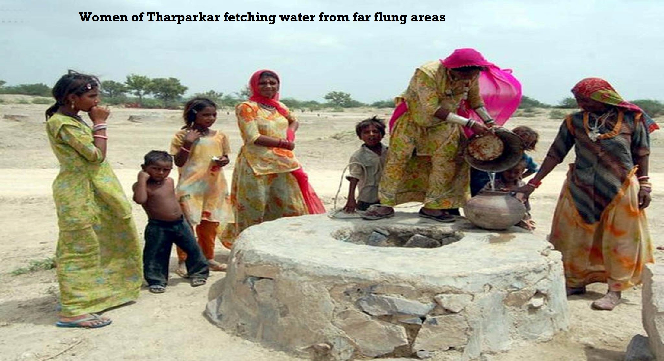
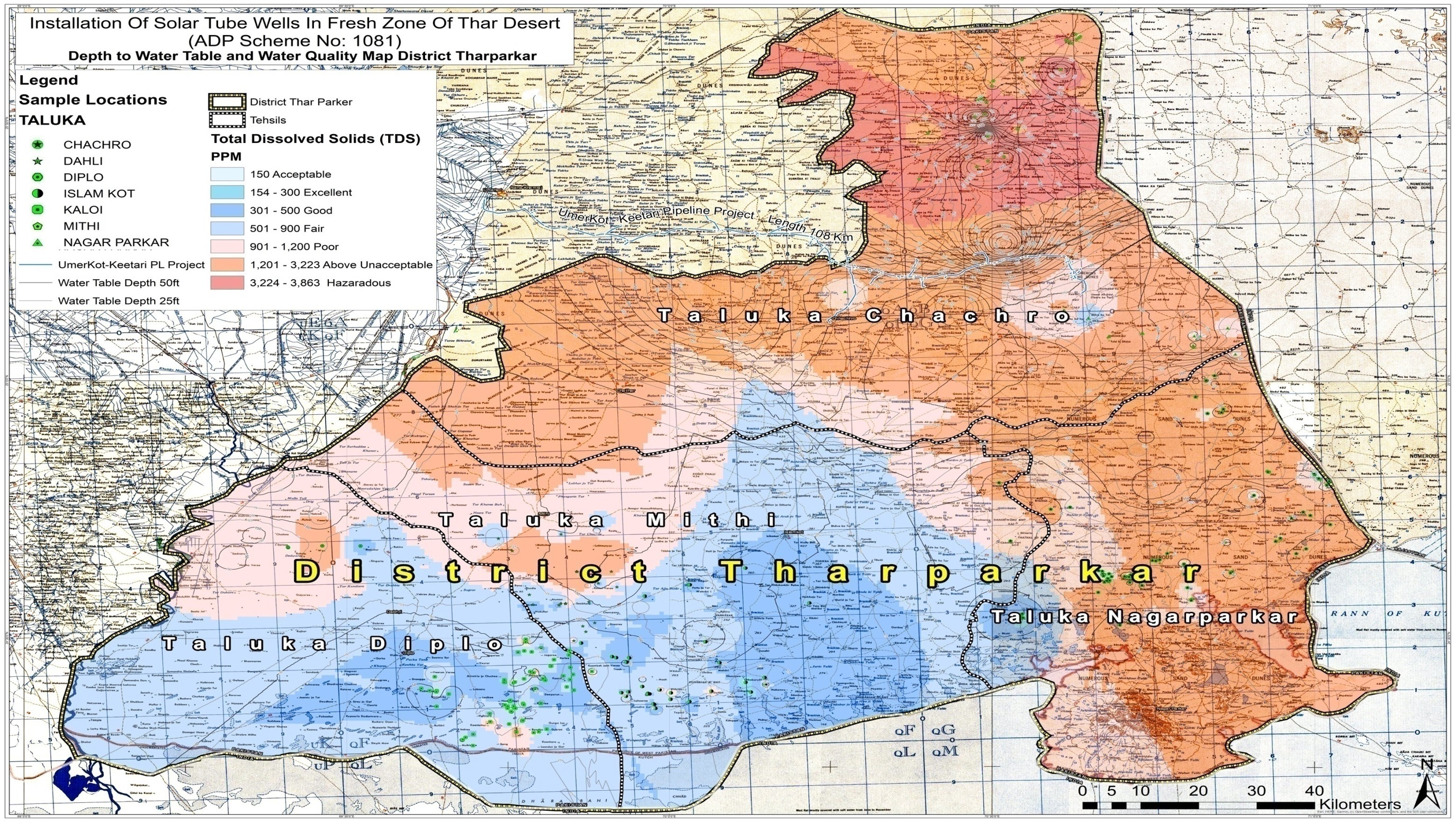
Over time, the rain ponds and wells in Tharparkar become contaminated with saline and arsenic, leading to major health issues and fatal diseases in the desert region. Water, being an essential element for the survival of mankind, remains a haunting scarcity for the people of Tharparkar. Every year, at least 400 children lose their lives due to malnutrition and waterborne diseases.
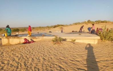
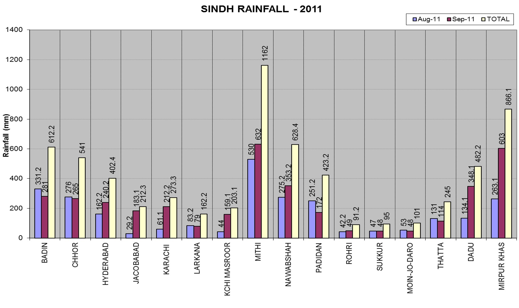
In Tharparkar, the only source of fresh water is the annual rainfall, which is limited to a mere 100-500 mm per year, mostly occurring between July and September. The people of Thar rely on storing rainwater in Tarais (small reservoirs) to sustain themselves throughout the year, but this supply is often insufficient. Women in Tharparkar undertake the arduous task of traveling 4 to 5 kilometers daily to fetch water on their shoulders from wells and Tarais.
To address these pressing challenges, the BENAZIR BHUTTO SWEET WATER PROJECT FOR THAR (UMERKOT TO KEETARI) has emerged as a ray of hope. This project aims to provide sweet, fresh water to 70 major villages in Thar, covering the area from Umerkot to Keetari. The project targets the current population of 231,010 individuals and anticipates serving the future population of approximately 500,000 people drawn from the Thar Canal.
The SHAHEED BENAZIR BHUTTO SWEET WATER PROJECT FOR THAR serves as a critical step forward in safeguarding the people of Tharparkar from impending catastrophe. By ensuring access to a sustainable and reliable source of fresh water, this initiative seeks to alleviate the hardships faced by the residents, improve their health outcomes, and contribute to their overall well-being.

| Tank capacity | Number of Tanks |
|---|---|
| 20,000 Gallons | 4 |
| 50,000 Gallons | 66 |
| 60,000 Gallons | 38 |
| 80,000 Gallons | 21 |
| Total | 129 |
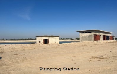
| No. of Pumps | 6 (4 operating, 02 standby) |
|---|---|
| Capacity of each pump | 88 L/sec at 6250ft Head |
| Each Pump Horse Power | 252 HP (250 KW) |
| Daily Water Requirement | 5.85 MGD |
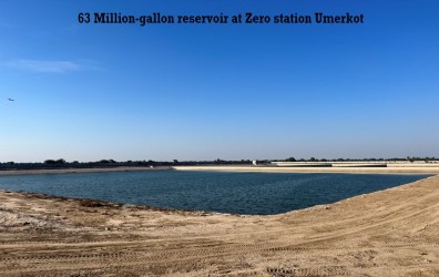
| Storage Reservoir Capacity | 63 MG(50 % requirement during closure) |
| No. of Pumps | 4 (3 operating, 01 standby) |
|---|---|
| Capacity of each pump | 137 L/sec at 550ft Head |
| Each Pump Horse Power | 74 HP (250 KW) |
| Daily Water Requirement | 2.50 MGD |
| Storage Reservoir Capacity | 19 MG |


